Tools and Supplies
* BayStar hydraulic steering kit
* Optional SeaStar spacer kit (might be required)
* Gear puller
* Socket-wrench set
* Box/open-end wrench set
* Masking tape and marker
* Pipe-cutter
* 1/4-inch cord (for messengers)
* Power drill and bits
* Jigsaw
* Thread sealant such as Loctite 592 PST ($5.29/0.20 ounce, advanceautoparts.com)
* Cleanup rags (to wipe up hydraulic fluid)
Hydraulic steering makes handling higher horsepower easier and smoother. Installing a system in your outboard-powered boat is a simple do-it-yourself project. The BayStar kit (part number HK4200A) from SeaStar Solutions (seastarsolutions.com) for outboards up to 150 hp is one of the least expensive ways to upgrade. It includes a helm pump, a front-mount cylinder and two sets of hydraulic tubing that you cut to length. This system requires a splashwell width of at least 21 inches. Other systems for larger and multiple engines are also available.
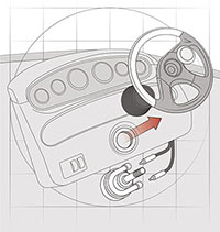
1. Remove the Cable System
Disconnect the steering cable at both the engine and helm by removing the retaining nuts, and remove the cable from the boat. Be careful to avoid snagging or damaging wires or throttle cables as you pull the steering cable out of the boat. Unbolt and remove the steering wheel, using a gear-puller if you need to break it loose from the helm spindle. Then unbolt and remove the helm.
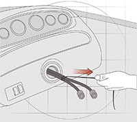
2. Pull the Hydraulic Tubes
Using your pull-cords (see “Quick Tip”), feed the hoses along the rigging path from the stern to the helm, making sure the swaged ends are at the stern end. Tape off the ends to keep out debris; also use masking tape and a marker to label the tubing at each end as “P” and “S,” to identify them later. Ensure that the tubing bends gradually throughout the run; do not exceed a four-inch bend radius.
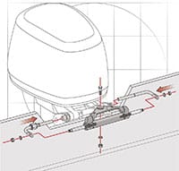
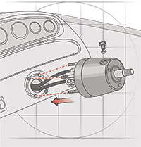
3. Install the Cylinder
Follow SeaStar’s instructions for installing the cylinder on your particular outboard (you might need an optional spacer kit). Once the cylinder is bolted in place, connect and snug up the tubing’s swaged compression fittings as follows: “P” to the starboard side of the cylinder, “S” to the port side (sounds wrong, but it’s correct). Make sure the tubing length will allow for the outboard’s side-to-side movement, as well as tilt and trim.
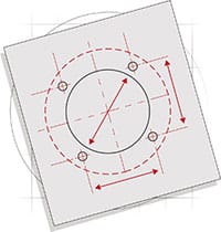
4. Create the Holes for the Helm
When mounted on top of the helm panel, the BayStar helm pump’s 4 5⁄8-inch-diameter base should cover the holes left by the mechanical helm. Use the supplied template to drill new holes for the mounting bolts and to enlarge the central hole to 3 inches using a jigsaw (though the existing hole might be big enough). Trial-fit the helm to ensure it does not protrude too much (see sidebar on adapters).
5. Connect Tubing to the Helm
Remove the helm and pull the tubing out through the central hole. Cut the tubing to length using a pipe-cutter and slide a tube nut over each end. Connect the “P” tube to the port side of the helm, “S” to starboard. Apply sealant to the threads. Hand-tighten the nuts, giving each 1 1/2 extra turns with a 5⁄8-inch wrench. Feed the tubing back through the central hole and mount the helm using the supplied hardware.
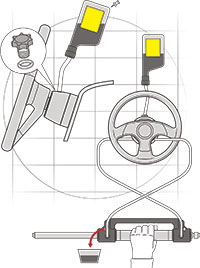
6. Fill and Bleed the System
With the helm and wheel installed, make sure the tubing is properly supported throughout its run. Then remove the cap on top of the helm pump, and use the supplied hydraulic fluid and filler kit to fill the system. Next, with the help of a friend, bleed the system of air. For detailed instructions on how to bleed a BayStar hydraulic steering system, visit boatingmag.com/how-to-bleed-hydraulic-steering.
Quick Tip: Securely tape two 1/4-inch pull-cords to the cable before you remove it; you can use these “messengers” (as old school riggers call them) to pull the hydraulic tubing back through the rigging channel.
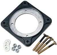
Helm Adapters
You can recess the helm using the Teleflex Helm Mounting Adapter (part number HA-5418, $34.99, westmarine.com). It will reduce the helm’s protrusion by the thickness of the dash panel; use a block behind the panel for a greater recess. It requires a larger central cutout and four bolt holes around the helm.


