Most boats benefit from a set of trim tabs from companies such as Bennett and Lenco. These devices can improve hole shot, bring the bow angle down for a smoother ride in choppy seas, correct for a list while underway, prevent porpoising and even improve fuel economy. Trim tabs with electric actuators (versus old-school hydraulic actuators) have simplified the installation process. We show how to choose and install a pair of Lenco Marine Standard Performance electric tabs on a 22-foot sterndrive-powered runabout.
Getting Started
Skill Level: 4.5/5
Time to Complete: 6.5 Hours
Tools and Supplies
- Lenco Marine 12-by-12-inch Standard Performance tabs
- Lenco double-rocker switch (if not included in kit)
- Pair of 26-foot extension cables
- Electric drill and drill bit set
- Box wrench set
- Socket wrench set
- Tape measure
- Straightedge
- 2-inch hole saw
- Phillips screwdriver set
- Sikaflex 291 or equivalent marine sealant
- Wire crimper/cutter
- Marking pencil
- Clean rags and rubber gloves (for cleaning up sealant)
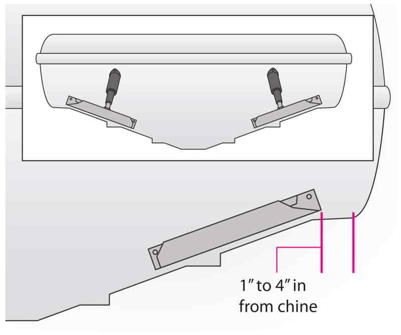
Position the Tabs
Locate the tabs as far to the outside of the transom as possible, with the inner edge of the tab no closer than 2 inches from a strake edge and the outer edge 1 to 4 inches from the chine. You need at least 11 inches of transom height for the Lenco 12-by-12-inch Standard Performance tabs used in this installation. Make sure the tabs are symmetrical — mirror images on each side.
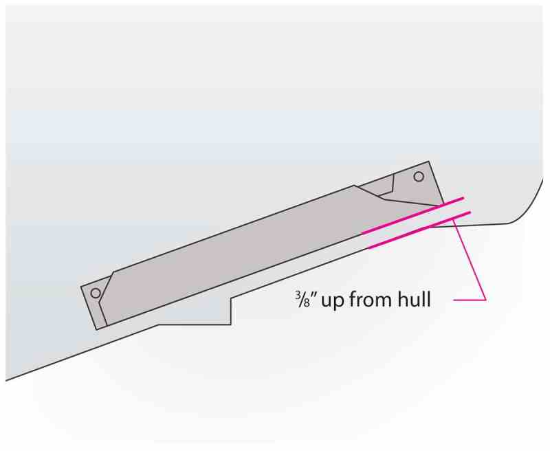
Mount the Tab
Position the bottom of the leading edge of each tab 3/8 inch above the bottom of the transom, making sure this dimension is consistent from one edge of the tab to the other. Mark the mounting holes and drill a 3/16-inch hole 1 1/4 inches deep for the self-tapping No. 14 mounting screws. Thoroughly bed each area with an adhesive sealant such as Sikaflex 291, and then attach the trim tabs.
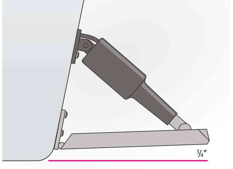
Position Each Actuator
Secure a straightedge against the bottom of the hull so that it extends under the tab. Bolt the bottom of the actuator to the tab, nuts on top. With the actuator fully retracted, place the mounting pad flat against the transom, sliding it up or down until the trailing edge of the tab is 3/4 inch above the straightedge. Mark the holes for the upper mount of the actuator. Ensure both tabs are mounted the same way.
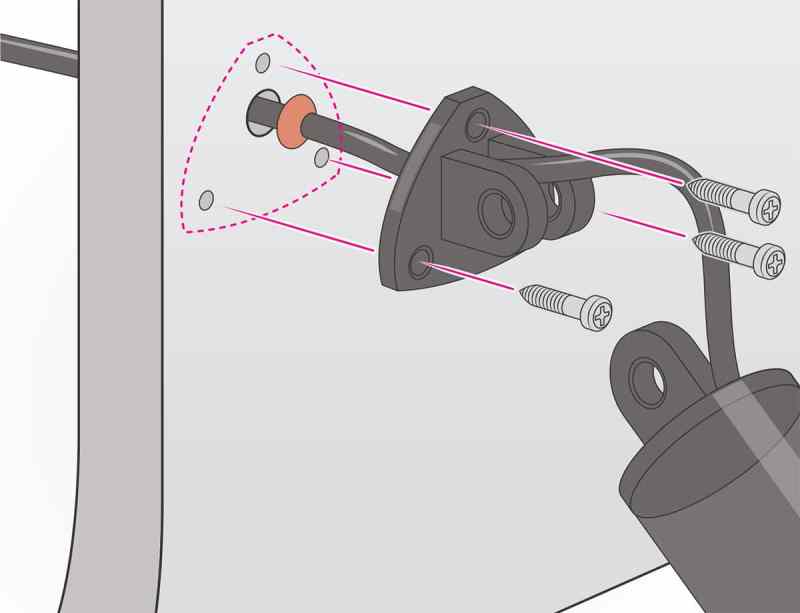
Install Actuators
Remove the upper mounting bracket, align the marks from step 3, and mark the cable hole location. Check for interference behind the transom, and then drill the 3/16-inch mounting holes 1 1/4 inches deep. Drill a 3/8-inch hole for the cable. Feed the cable through the mounting pad, slide the gland seal over the cable, and feed the cable through the transom. Bed and install the bracket with the No. 14 screws. Attach the actuator to the upper bracket.
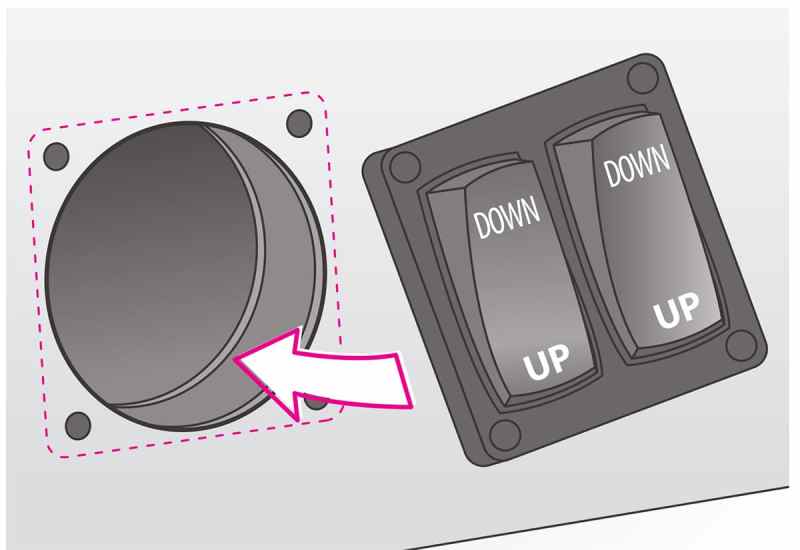
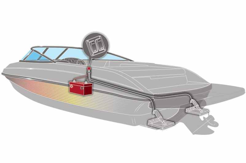
Install the Switch Panel
After pulling the actuator cables snuggly through the transom and attaching them to the cable extensions, snake the two cable extensions to an area behind the helm or console. Select a vertical or angled surface that’s easy to reach from the helm to install the double-rocker switch panel (sold separately). Use the supplied template to mark the location. Check the area behind for interference; then use a 2-inch hole saw to cut the main hole. Drill the four 1/8-inch holes. Install the control pad with the supplied self-tapping screws.
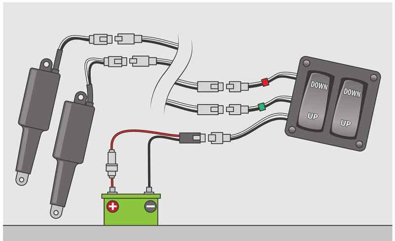
Wire the Switch Panel
Follow the supplied wiring diagram to connect the actuator cable extensions to the cable plugs on the back of the rocker switch panel, making sure starboard (with green tape) and port (red tape) cables are plugged into the correct connectors. Run the positive and negative power leads to the battery, with a 20-amp breaker or fuse for the positive wire. Test the tabs to make sure they are wired correctly. Be aware that the port rocker operates the starboard tab and vice versa. Thus, pushing “down” on the port rocker lowers the port bow and vice versa.


