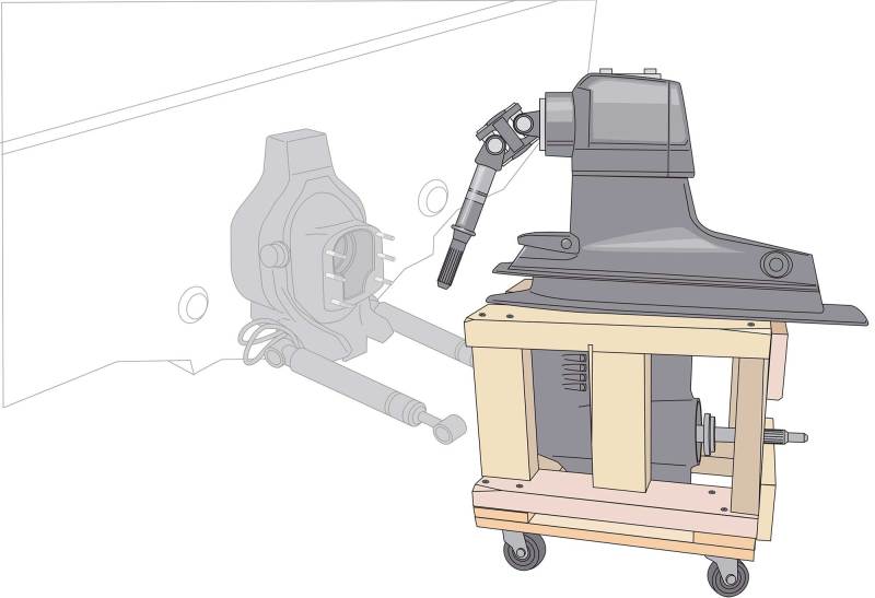
Once detached from a marine engine, a sterndrive or outboard lower unit is unwieldy and heavy, making repairs and storage awkward at best. Some boaters use bench vises to grip the skeg and keep lower units upright while undertaking work, but this is best reserved for smaller outboard lower units, and even at that, it risks breaking or bending the skeg.
The best solution is a sterndrive/lower-unit stand. You can buy top-quality models from companies such as Stumpy’s Fab Works for about $210. But unless you’re a full-time marine mechanic, it might not be worth the investment.
Another option is to build your own. While there are a number of ways you can engineer and build a stand, here’s one of the least expensive approaches based on a 12-by-18-inch-wide store-bought dolly, but you can adapt the plans to suit a larger dolly, say an 18-by-24-inch model, if this version seems too “tippy” for the size of your drive. Costing about $40 in materials, construction relies on lumber, readily available tools and rudimentary carpentry skills.
Skill Level: 2 of 5
Finish Time: Approx. 4 hours
Tools and Supplies
• Two-by-four common redwood lumber, 15 to 20 feet ($12.27 per 10-foot board, homedepot.com)
• One-by-four poplar board, 2 feet ($3.82 per 8-foot board, homedepot.com)
• 12-by-18-inch hardwood dolly ($10.99, harborfreight.com; adapt your plans to a larger dolly if this size will not be stable enough for your drive)
• 3-inch-long coarse drywall screws
• Power driver with Phillips-head bit
• Electric chop saw
• Measuring tape
• Outside caliper
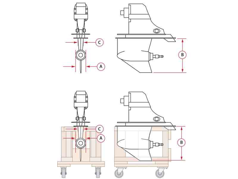
The dimensions of lower units vary with type (sterndrive vs. outboard), brand and engine size. So the first step is to ascertain three key dimensions: a) the width of the cylindrical gear case; b) the vertical distance from the bottom of the anti-aeration plate to the bottom of the skeg; and c) the maximum width of the lower-unit housing directly below the anti-aeration plate. Use an outside caliper to measure a and c.
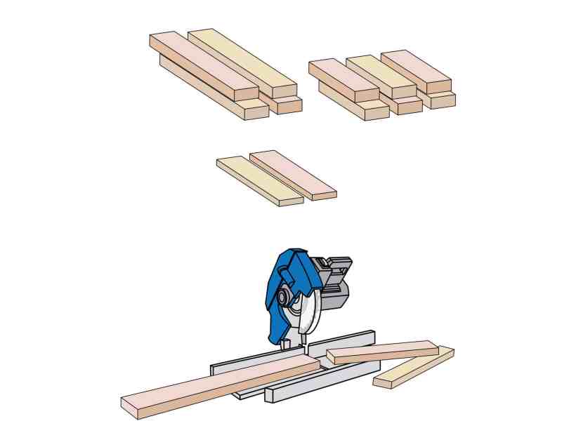
Using two-by-four boards, cut four 18-inch sections to serve as the base and top of the stand. Then cut six sections for the uprights. The length of these should all be the same as the distance between the bottom of the anti-ventilation plate and the bottom of the skeg. The bottom and top two-by-fours (lying flat) will add 3 inches total to the height. Also cut two 12-inch sections from a one-by-four piece of lumber for bracing the uprights.
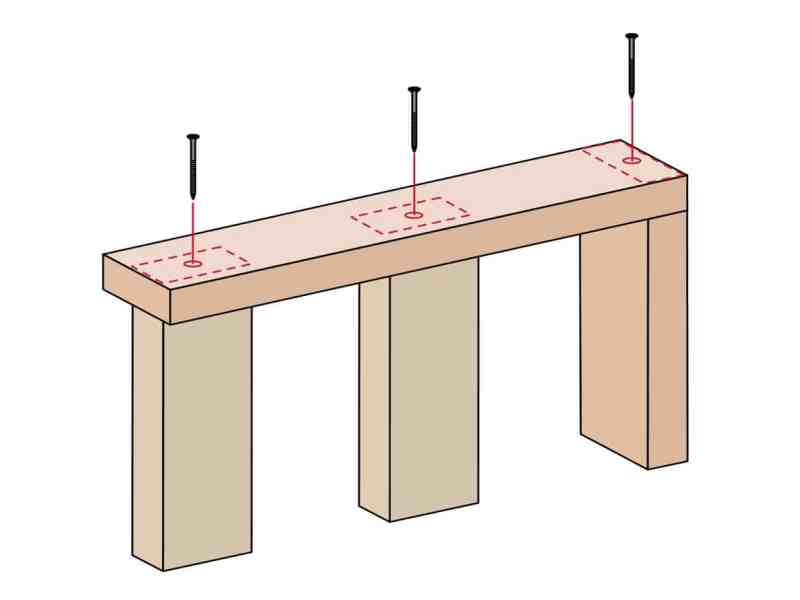
Build each side of the stand with one 18-inch two-by-four laid flat for the base. Use 3-inch drywall screws and a power driver to fasten one upright atop one end, and the other two (at the midpoint and other end) turned 90 degrees. Each side should be a mirror image of the other. The stand will be 12 inches wide at the base. Install the latter two uprights outward enough to allow room for the gear case to fit between them.
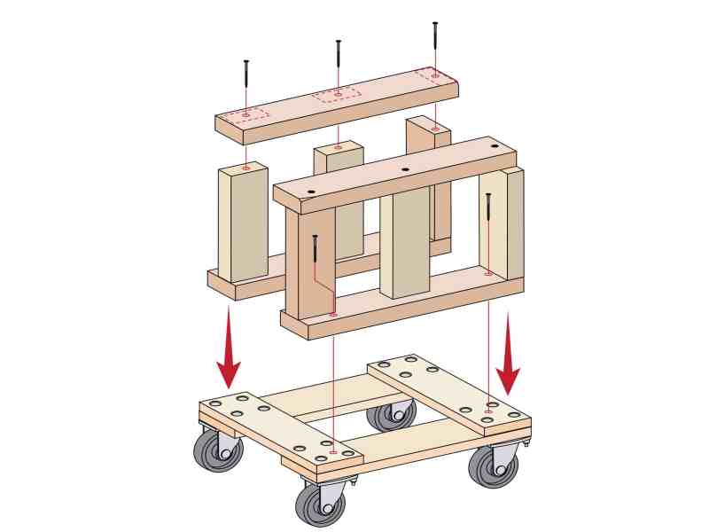
For the rolling base, use a store-bought 12-by-18-inch hardwood dolly. Fasten the sides of the stand parallel to each other and along the edge of the long sides of the dolly. Test to ensure the gear case fits inside. Attach the remaining two 18-inch sections to the tops of the uprights, parallel and just wide enough for the slender section of the lower unit just below the anti-aeration plate to slide through. Test the fit again.
Read Next: Replacing a Stern-Drive Bellows
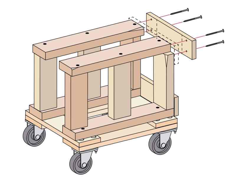
One end of the stand will remain open (like a tuning fork), but the other should be braced with two 12-inch cross sections of the one-by-four lumber for lateral support. Fasten one brace to the top and one to the bottom of the end with the square-mounted uprights. In this configuration, there should be room for the prop shaft to protrude outward between the two braces. If not, notch the brace to make room for the shaft.


