Marine thermal-imaging systems detect heat signatures of objects – the infrared light that’s invisible to the human eye. The technology lets you see the surrounding waters and spot potential hazards at night, even in complete darkness. Such systems also let you see low-lying obstacles in the dark, such as floating timbers and lobster-pot buoys that marine radar cannot pick up.
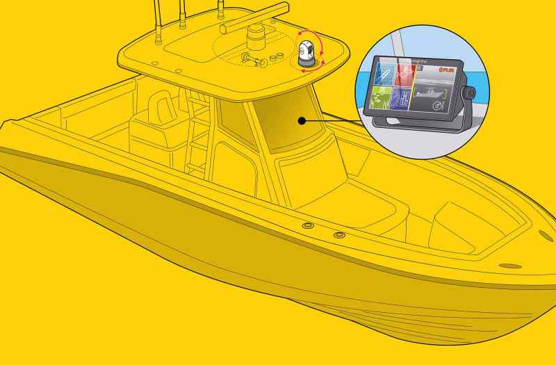
Fixed-mount thermal-imaging cameras from brands such as FLIR and Iris come in a wide range of models and prices, and all will network with a touchscreen multifunction display for viewing and control. For this project, we chose the FLIR M232, featuring a single 320-by-240 imaging system with pan, tilt and zoom functions. It is currently compatible with Garmin GPSMap and Raymarine Axiom series MFDs.
While there a number of possible configurations, for this project, we chose an Axiom display. This not only simplifies the project, but it also offers the ability to access the FLIR ClearCruise intelligent thermal-analytics feature. Raymarine and FLIR are sister brands.
Skill Level: 2 of 5
Finish Time: Approx. 4 hours
Tools and Supplies
• FLIR M232 thermal- imaging camera ($3,499, thegpsstore.com)
• Optional JCU-3 joystick control ($369.95, thegpsstore.com)
• Optional RayNet HS5 network switch ($259.95, thegpsstore.com)
• Optional RayNet-to-RayNet cable
• Power drill and set of drill bits
• 2-inch-diameter hole saw
• Open-end/box wrench set
• Thread-locking compound
• Electricians snake (for routing cables)
• Assorted marine crimp connectors with heat-shrink collars
• Heat-shrink tubing
• Wire strippers and crimping tool
• Heat gun (for heat-shrink connectors)
• Masking tape (to secure templates)
• Jigsaw (for JCU-3 install)
• Phillips screwdriver (for JCU-3 install)
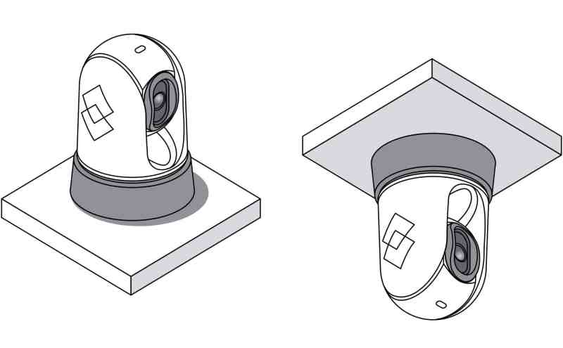
Most thermal cameras are mounted on the leading edge of a cabin roof or hardtop to ensure an unobstructed forward field of view. Ball-up (upright) installs are most common (as shown here); ball-down (hung upside down from a brow, for example) is an option, but it negates the use of the ClearCruise thermal-analytics feature. Suppled hardware is adequate for mounting surfaces as thick as 1.6 inches. Use shorter or longer mounting studs or bolts to accommodate different thicknesses. Make sure you have sufficient access to route the required power and network cables, and that the camera doesn’t interfere with the rotation of any radar arrays.
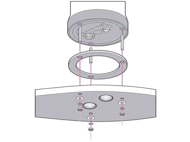
Use the supplied template (make sure that the template is oriented properly relative to the bow) to mark and drill the three mounting holes. Use a hole saw to cut two cable access holes. Install the mounting studs in the base of the camera using a thread-locking compound to ensure that these fasteners do not vibrate loose over time. Install the O-ring on the base of the camera, and connect the two cables to the ports at the bottom of the camera. Insert the cables from the bottom of the camera through the cable access holes, then place the camera so the studs extend through the mounting holes. Secure the camera with the supplied nuts and washers.
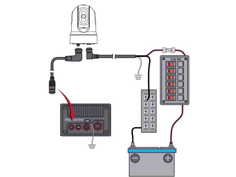
Use the included power and RayNet-to-RayNet cables (both 10 meters long). Route the triplex power cable (the M232 accepts both 12- and 24-volt DC) from the camera to the following points: positive/red wire to a powered onboard circuit breaker (add a 5-amp fuse for 12-volt systems); negative/black wire to a negative bus bar; bare “drain” wire to ship’s ground. Use marine crimp connectors with heat-shrink collars for terminal connections. Cover each crimp with heat-shrink tubing for additional waterproofing and durability. Route the RayNet cable from the camera to the Axiom series MFD and connect to the network receptacle on the back of the MFD.
Read Next: The Basics of Thermal-Imaging Cameras
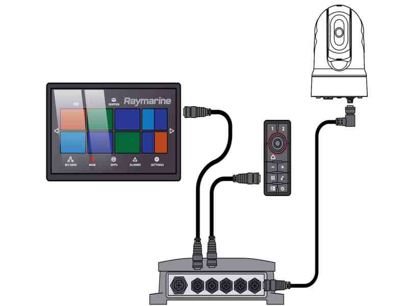
The M232 can be operated solely from the networked Axiom touchscreen MFD (with LightHouse 3 software), but you can also add an optional FLIR joystick control unit such as the JCU-3 for a second means of controlling camera functions such as pan, tilt and zoom. It is supplied with two key faces for a vertical or horizontal orientation. The JCU-3 requires a RayNet HS5 network switch and an additional RayNet-to-RayNet cable. The JCU-3 and network switch must both be connected to DC power. Select an easy-to-reach spot on the dash to flush- or surface-mount the JCU-3, and use the supplied template and instructions to install it.


